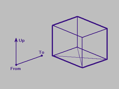
Figure 3.1
The 3D Viewing Vectors and From, To Points
Before describing the rendering methods for four-space visualization, we need to establish a viewing model that adequately describes a view of and in four space. This view needs to account for position of the viewpoint, direction of view, and the orientation of the scene from the viewpoint (or, conversely, the orientation of the viewer).
This chapter contains only the concepts of viewing in three- and four-space; the mathematical and implementation details are presented in chapter 4 and chapter 5.
Before attacking the four dimensional viewing model, let's review the viewing model for three dimensions (presented in [Foley 87]).
The first thing to establish is the viewpoint, or viewer location. This is easily done by specifying a 3D point in space that marks the location of the viewpoint. This is called the from-point or viewpoint.
The next thing to establish is the line of sight (where we're looking). This can be done by either specifying a line-of-sight vector, or by specifying a point of interest in the scene. The point-of-interest method has several advantages. One advantage is that the person doing the rendering usually has something in mind to look at, rather than some particular direction. It also has the advantage that you can ``tie'' this point to a moving object, so we can easily track the object as it moves through space. This point of interest is called the to-point.
Now that we've established the line of sight, we need to pin down the orientation of the viewer/scene. This parameter will keep us from looking at a scene upside down, for example. To do this, we specify a vector that will point straight up after being projected to the viewing plane. This vector is called the up-vector. Since the up-vector specifies the orientation of the viewer about the line-of-sight, the up-vector must not be parallel to the line of sight. The viewing program uses the up-vector to generate a vector orthogonal to the line of sight and that lies in the plane of the line of sight and the original up-vector. See figure 3.1 for a diagram of the 3D viewing vectors.
If we're going to use perspective projection, we need to specify the amount of perspective, or ``zoom'', that the resultant image will have. This is done by specifying the angle of the viewing cone, also known as the viewing frustum. The viewing frustum is a rectangular cone in three-space that has the from-point as its tip, and that encloses the projection rectangle, which is perpendicular to the cone axis. The angle between opposite sides of the viewing frustum is called the viewing angle. It is generally easier to let the viewing angle specify the angle for one dimension of the projection rectangle, and then to tailor the angle of the perpendicular angle of the viewing frustum to match the other dimension of the projection rectangle.
The greater the viewing angle, the greater the amount of perspective (wide-angle effect), and the lower the viewing angle, the lower the amount of perspective (telephoto effect). The viewing angle must reside in the range of 0 to pi, exclusive.
Refer to figure 3.3 for a diagram of the viewing parameters and viewing frustum in three dimensions. The angle from D to From to B is the horizontal viewing angle, and the angle from A to From to C is the vertical viewing angle.
To render a three-dimensional scene, we use these viewing parameters to project the scene to a two-dimensional rectangle, also known as the viewport. The viewport can be thought of as a window on the display screen between the eye (viewpoint) and the 3D scene. The scene is projected onto (or ``through'') this viewport, which then contains a two-dimensional projection of the three-dimensional scene.
To construct a viewing model for four dimensions, we extend the three-dimensional viewing model discussed in section 3.1 to four dimensions.
Three-dimensional viewing is the task of projecting the three-dimensional scene onto a two-dimensional rectangle. In the same manner, four-dimensional viewing is the process of projecting a 4D scene onto a 3D region, which can then be viewed with regular 3D rendering methods. The viewing parameters for the 4D to 3D projection are similar to those for 3D to 2D viewing.
As in the 4D viewing model, we need to define the from-point. This is conceptually the same as the 3D from-point, except that the 4D from-point resides in four-space. Likewise, the to-point is a 4D point that specifies the point of interest in the 4D scene.
The from-point and the to-point together define the line of sight for the 4D scene. The orientation of the image view is specified by the up-vector plus an additional vector called the over-vector. The over-vector accounts for the additional degree of freedom in four-space. Since the up-vector and over-vector specify the orientation of the viewer, the up-vector, over-vector and line of sight must all be linearly independent.
The viewing-angle is defined as for three-dimensional viewing, and is used to size one side of the projection-parallelepiped; the other two sides are sized to fit the dimensions of the projection-parallelepiped. For this work, all three dimensions of the projection parallelepiped are equal, so all three viewing angles are the same.
Figure 3.4 shows the projection of a 4D viewing frustum.